The short version
- Two instances of chip resistor cracking were identified during thermal cycling tests on identical printed circuit board assemblies.
- Investigations ruled out manufacturing defects and vibration fatigue, pointing instead to mechanical stress from board bending.
- New guidelines recommend finite element analysis and controlled soldering to mitigate risks for ceramic components near board edges.
NASA has issued a new technical bulletin addressing the unexpected failure of chip resistors in space-grade electronic assemblies. The guidance stems from two specific incidents where thick-film chip resistors suffered structural cracking during environmental acceptance testing. These failures occurred on printed circuit boards that had previously undergone vibration testing, with the fractures manifesting during subsequent thermal cycling phases. The agency’s Network and Space Communications Division highlighted these events to update engineering practices for handling ceramic body components.
The affected resistors are widely utilized across NASA projects due to their reliability and compact size. Despite their ubiquity, historical data indicated that cracking of the alumina substrate during standard environmental tests was exceedingly rare. The two observed failures involved identical boards with resistors installed in similar positions near the edges. In both cases, the components exhibited intermittent open circuit failures at high temperatures, which resolved when the systems returned to room temperature. This behavior suggested a mechanical rather than an electrical origin for the disruption.
Initial investigations considered the possibility of a defective production lot, as both failed resistors originated from the same batch. However, rigorous testing confirmed that the components met all requirements of the MIL-PRF-55342 procurement specification. Additional analyses found no evidence of elevated defect rates within the lot or any pre-existing flaws in the individual resistors. Consequently, engineers ruled out manufacturing defects as the root cause, shifting focus to external mechanical stresses acting upon the components during testing.
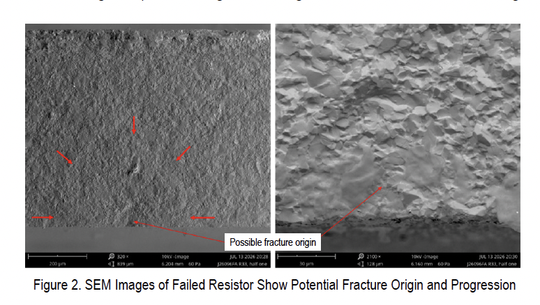
Failure analysis revealed that the cracks ran transversely across the short axis of each resistor, perpendicular to their long axis. This fracture pattern is characteristic of bending or tensile failure rather than twisting or shear stress. Independent optical and scanning electron microscopy examinations failed to identify clear initiation sites for fatigue damage. The absence of cyclic fatigue signatures made it unlikely that vibration testing alone caused the cracks, further supporting the hypothesis that board flexure played a critical role.
The investigation concluded that several contributing factors increased the risk of failure. These included the orientation of the components, excessive solder fillet height, and mounting stresses induced by the printed circuit board itself. Boards located near edges are more susceptible to bowing or twisting during manufacturing and installation processes. This deformation can transfer significant stress to large footprint ceramic components, leading to cracking even in the absence of material defects.
To mitigate these risks, NASA recommends a series of design and assembly guidelines. Engineers are advised to perform finite element analysis to predict stress concentrations on printed circuit boards before finalizing component placement. Careful attention should be paid to the orientation of resistors relative to expected board flexure directions. Additionally, controlling solder fillet height can reduce mechanical leverage that exacerbates bending stresses on the ceramic bodies.
The bulletin also emphasizes the importance of thorough inspection and functional thermal shock testing for assemblies containing sensitive ceramic components. These measures aim to detect potential vulnerabilities early in the development cycle. By implementing these practices, NASA seeks to prevent similar failures in future missions while maintaining high standards for electronic reliability in harsh space environments.
This update reflects a broader effort within the aerospace industry to refine manufacturing and testing protocols based on empirical data. While chip resistors remain a staple in electronic design, their vulnerability to mechanical stress underscores the need for holistic system-level analysis. The findings serve as a reminder that component reliability depends not only on material quality but also on how those materials are integrated into larger assemblies.
For further information regarding these technical guidelines, NASA has designated Joel W. Sills at the Langley Research Center as the primary contact. The agency continues to monitor environmental testing outcomes to ensure that emerging failure modes are addressed promptly. This proactive approach helps safeguard mission-critical systems against unforeseen mechanical challenges.
Sources behind this briefing
Go to the original reporting
- NASA↗TB 26-10 Printed Circuit Board Assembly Chip Resistor Body Cracking